SUMMARY
Electric submersible pumps (ESPs) make up a significant percentage of the artificial lift market. (“Artificial Lift Systems Market Size,” 2020). However, ESP technology is prone to failure, requires frequent maintenance, and requires expensive overhaul and downhole repairs. High Pressure Gas Lift (HPGL) is a more reliable, less complicated and cheaper alternative for onshore, unconventional oil and gas wells. New technology continues to make HPGL a practical and sensible option for onshore oil recovery.
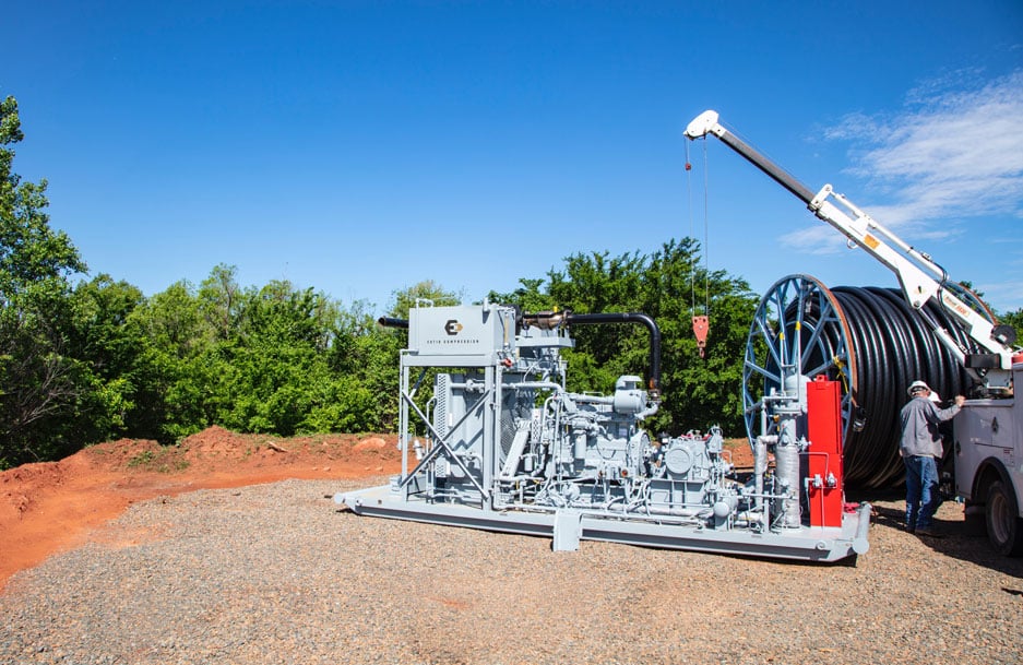
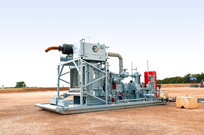
The use of gas lift, both conventional and single-point HPGL, offers numerous advantages over ESPs. Single-point HPGL, in particular, offers the greatest advantages in terms of simplicity, cost, and efficiency. HPGL is a streamlined, low-maintenance artificial lift method that produces fluid lift rates comparable to ESPs at a fraction of the installation, maintenance and repair costs. Estis Compression is a leader in the oil and gas industry and an expert in wellpad compression. Estis’ HPGL compressors maximize uptime, production and profit.
This article will examine several methods of artificial gas lift and artificial lift in general as a means of improving oil production and recovery. In each case, the history, operational mechanics, and limitations of the technology will be highlighted. The purpose is to demonstrate that when it comes to ESP vs. High Pressure Gas Lift, HPGL is a superior method of oil recovery at the forefront of a burgeoning trend.
UNDERSTANDING ARTIFICIAL LIFT METHODS
Artificial lift methods facilitate fluid production from a reservoir. Artificial lift aims to reduce the weight of the hydrostatic column in the wellbore, reducing the bottom hole pressure (BHP) and thereby increasing the rate of fluid influx from the reservoir. This can be done with either mechanical assist devices, in which motors or impellers are used to force oil up the wellbore, or by formation pressure technology, which aims to either decrease oil-column density or decrease hydrostatic pressure to facilitate flow.
Artificial methods of pumping fluids to the surface include ESPs, rod pumping, plunger lift and gas lift. (“Artificial Lift Methods,” 2020). There is a trend toward designing infrastructure that can handle high-pressure applications, largely due to the needs of the hydraulic fracturing industry. This reinforcement of wells and tubing makes it possible and economical to implement HPGL lift in onshore wells.
Over ninety-five percent of wells utilize artificial lift, as natural flow only occurs during the initial stages of a well’s production life (Amao, 2013). When reservoir pressures drop too low, the well can no longer overcome the weight of the hydrostatic column. At this point, production is slow and ceases to be economical. Another case where artificial lift is necessary is when liquid loading occurs. During loading, reservoir fluids cannot enter the wellbore due to the hydrostatic pressure of the liquid column. Well production slows or ceases, and artificial lift systems are required.
ELECTRIC SUBMERSIBLE PUMPS
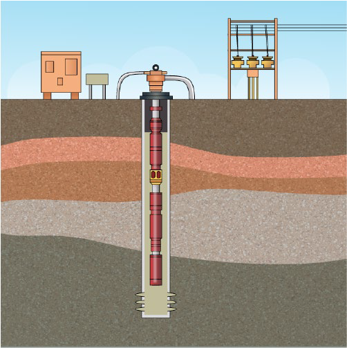
ESPs are a widely used and generally trusted method of artificial lift. The first ESPs were developed in the late 1920s and used in oil fields by the predecessor to Pleuger Industries. ESPs were developed by a young Armenian engineer, Armais Arutunoff, who invented the first waterproof electric motor. Using an idea that stemmed from that invention, he developed a technology that could be used for oil recovery (“Electrical Submersible Pumps,” 2020). ESPs rapidly spread throughout Texas, Oklahoma, and California. From there, they became the most common method of alternative lift in the world.
The general idea behind an ESP is that a motor is coupled to a pump body and hermetically sealed. The entire unit is submerged in the oil, connected to power supplies and operator controls via a series of submersible cables (Ibid.) ESPs are especially effective in wells with low bottomhole pressure (BHP), low gas/oil ratios, low bubblepoint, high water cut, or low API gravity fluids (“Artificial lift methods,” 2020). They are typically not affected by well depth but are limited by horsepower, temperature, and cable length. Therefore, practical depth limitation is about 10,000 ft.
Despite their ubiquity, ESPs are highly susceptible to wear and damage. Sand is one of the largest causes of failure to the ESP, as sand particles damage impellers in the pump, which spin at a rate of about 3600 RPM. Sand screens are necessary to prevent early pump failure, but these components require additional maintenance and frequent replacement. Fluid separators are also needed at the intake to separate gas, oil and water (Lyons, 2016). When the percentage of gas exceeds roughly 10% volume at the pump, the effciency of the ESP is significantly impaired. Additionally, high AC voltages, on the order of 3 to 5 kV, are necessary to drive the motor. As a result, a major expense of ESP in off-grid wells goes to operating diesel-powered engines. Finally, ESPs require well intervention that is typically necessary every four to twelve months. They are also limited to a temperature of less than 250 degrees Fahrenheit. It is apparent that despite their popularity, ESPs introduce a number of problems that hamper well productivity and uptime.
ROD PUMPS
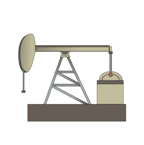
The iconic visual of a Texas oil-field is one populated by the bobbing and rocking of rod pump horse-heads. Rod pumps, also known as beam pumps, are probably the most well-known images associated with the oil and gas industry. In fact, they are the oldest method of artificial lift oil production (“Sucker Rod,” 2020). The mechanics and calculations required to design and operate a rod pump are relatively simple as they are based on a four-bar linkage system. This makes them highly adaptable and customizable, an ideal combination for early well developers.
Rod pump operation is simple. A down-hole plunger oscillates when a motor activates the horse-head system. A series of rods submerge and withdraw the plunger, displacing fluid within the tube wall. Their operating temperature range tops over 500 degrees Fahrenheit, making sucker rod pumps suitable for lifting high temperatures and high viscosity oils. Surveillance and monitoring of this type of lift system is exceptionally easy to perform with dynamometers and remote computer monitoring. Intake is also exceptional, with less than 25 psi (50-100 psig) needed for ideal displacement and adequate venting.
Sucker rods are limited by well depth. For a well less than 2500 ft. deep, the pump must be landed below the dynamic fluid level. The maximum depth is around 14,000 ft. Another drawback to the rod pump is the high frequency of workovers and maintenance. Rod strings can begin to fail in as little as six to eight months, with an average expectancy of about a year and a half. Corrosion, wax, asphaltenes and other solids must be controlled adequately to ensure the pumps run at maximum efficiency.
PLUNGER LIFT
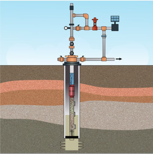
The plunger lift was developed as a way to control liquid loading. Deliquification is an important part of the pumping process. Failure to deliquify properly can slow or even stop well production. The plunger lift uses the well’s own pressure or gas flow rate to lift liquids to the surface and remove them from the tubing.
A tube is seated into the well and the plunger creates a seal with the tube’s interior wall. During periods of optimal flow rates, the plunger rests at the top of the well. Over time, as production levels fall, liquid accumulates at the tube end. This is the beginning of liquid loading. When loading occurs, the decrease in pressure causes the plunger’s valve to close, and the plunger falls to the bottom of the tubing. This forms a seal in the well, and pressure begins to rise. The plunger rides this pressure back to the top of the well, delivering the accumulated liquid to the surface and restoring the well to prime operating conditions.
The plunger lift system can be used to remove several types of contaminants from natural gas wells. These include water, sand, and oil. However, lubrication is required to form a good seal and to allow the plunger to travel easily through the tube. Plunger lifts differ from other artificial gas lifts in that they primarily maintain optimal conditions rather than directly facilitate the movement of the gas.
CONVENTIONAL GAS LIFT
Conventional gas lift is one of the oldest methods of artificial lift in the United States. The earliest implementations of gas lift date back to the mid-1800s, when the system was first introduced in Pennsylvania. During the Texas oil boom of the 1930s and 40s, multi-stage gas lift was developed, which was the basis for conventional gas lift as we know it today. The technology allowed for extended oil recovery in mature wells operating at low pressure (Bin Jadid, 2006).
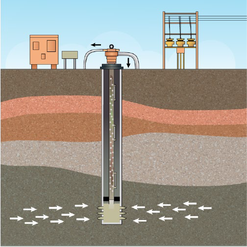
Conventional gas lift injects gas directly into a column of hydrostatic fluid, truncating the column and decreasing its overall density. Gas is inserted into the tubing via valves in the mandrels. Gas flow from these valves breaks the column of fluid into smaller pieces. As the density of the column is decreased, the natural energy gradient of the well remains sufficient to transport the liquid to the surface. Conventional gas lift is capable of enormous lift capacity and has proved to be a very effective and reliable artificial lift method.
In order to maintain maximum efficiency, maintenance of the gas valves is necessary. Also, as reservoir parameters change, gas-lift valves may require resettling. In some cases, the tube string may require replacement. Finally, CO2 and H2S contaminants must be kept in check to ensure proper bellows functioning. The stress of continuous use may fatigue the mechanical elements in a conventional gas lift system. With proper maintenance, however, well operators can reduce wear and tear and cut down on service costs (Elmer, 2019).
HIGH PRESSURE GAS LIFT
HPGL has been a popular method of artificial lift in deepsea drilling for years. Up until recently, however, it was not practical for use on onshore wellpads. This changed when the requirements of hydraulic fracturing led to new, advanced, and widely available materials. Casings in horizontal wells have seen a structural redesign making them capable of handling well over 10,000 psi. This increase in durability makes HPGL more viable and desirable. Additionally, compressor cylinders designed for compressed natural gas have also seen design overhauls and many can now handle up to 6000 psi. These advancements eliminate the need for total reliance on conventional gas lift, with its numerous lift valves and fail points, making HPGL a streamlined, low-maintenance artificial lift method.
Wellpad maintenance and cascading efficiency is a concern for every well. HPGL is the solution. HPGL can provide up to three times the injection pressure using precision-engineered surface compression technology. Estis Compression engineers have designed a surface compressor that makes it possible to utilize an artificial gas lift method that used to be limited to offshore wells.
High pressure gas is injected from the surface, so all operations can be addressed above ground. Zero downhole intervention is required during installation and throughout the operation of the HPGL system. This is a significant improvement over conventional gas lift designs. According to the conclusions of a study conducted by the Society of Petroleum Engineers (SPE-195189-MS), HPGL delivers a rate of flow comparable to ESPs. The primary benefit of HPGL, sometimes called single point HPGL, is just what the name suggests—it’s a single point. Rather than successively activating gas lift valves installed throughout the the tubing string, gas is simply injected through a single point at the bottom of the tubing (either through the tubing or the annulus). That means there are no valves to repair, replace or maintain. Fewer moving parts, fewer points of failure, and reduced maintenance mean more uptime and maximum productivity. Consequently, Estis Compression systems provide a significant uplift in production potential.
ESP VS. HIGH PRESSURE GAS LIFT
The final point to make in this comparison of artificial lift methods is to compare the reigning champion, ESP, with the emerging and promising HPGL technology featuring wellhead compression. How do they stack up on the points of reliability, simplicity, and cost-effectiveness?
What is immediately clear is that ESPs are prone to failure, especially in wells that have been fractured with large quantities of sand. They have short lives, sometimes just a matter of weeks. The cost of replacing an ESP can run upwards of a quarter of a million dollars and the estimated cost to operate a horizontal, unconventional well through the initial flow phase may exceed half a million dollars. The high voltage needs, short life and costly operation have been tolerated due to high yields and impressive flow rates.
HPGL using advanced wellhead compression is more reliable, less complicated, and a cheaper alternative to ESP while producing similar yields. Brandon Pronk, in SPE 195180-MS, showed that HPGL flow rates are comparable to those of ESPs. This led Pronk to go a step further and appraise the cost of installing and operating ESPs vs. HPGL. He found that the capital requirement for HPGL was around two-hundred and fifty thousand dollars less than ESPs. Additionally, the monthly operational costs for HPGL are significantly lower. Finally, HPGL requires no downhole maintenance, features minimal points-of-failure, and offers a simpler design than ESPs. In short, HPGL costs less in time, capital, and maintenance than ESPs.
ESPs are currently the industry standard for unconventional, horizontal oil recovery. HPGL, still a new technology for onshore artificial lift oil production, is an emerging trend. However, HPGL provides well operators with a superior product. It is more dependable, requires less maintenance, and is more economical. HPGL also offers fluid lift rates comparable to ESPs. With companies like Estis making wellhead compression affordable, customizable, and reusable, the industry standard is surely on the cusp of change.
REFERENCES
[1] Artificial lift system market size, share | Industry Report 2026. (n.d.). Retrieved August 3, 2020, from https://www.fortunebusinessinsights.com/industry-reports/ artificial-lift-system-market-100467
[2]Artificial lift methods overall comparisons | Petroleum Reservoir | Pump. (n.d.). Retrieved August 14, 2020, from https://www.scribd.com/document/296335446/ artifcial-lift-methods-overall-comparisons
[3] (Artificial lift systems). (2013). Retrieved August 14, 2020, from https://pdfs. semanticscholar.org/e2bd/3fcb811feedb505d29caf9cbb21b2110766b.pdf
[4] Electrical submersible pumps - PetroWiki. (n.d.). Retrieved August 14, 2020, from https://petrowiki.org/Electrical_submersible_pumps
[5] Lyons, W. C., Plisga, G. J., & Lorenz, M. D. (2016). Preface (W. C. Lyons, G. J. Plisga, & M. D. B. T.-S. H. of P. and N. G. E. (Third E. Lorenz (Eds.); pp. xi–xii). Gulf Professional Publishing. https://doi.org/https://- doi.org/10.1016/B978-0-12-383846-9.09998-7
[6] Sucker rod - an overview | ScienceDirect Topics. (n.d.). Retrieved August 3, 2020, from https://www.sciencedirect.com/topics/engineering/sucker-rod
[7] Bin Jadid, M., Lyngholm, A., Opsal, M., Vasper, A., & White, T. M. (2006). The Pressure’s On: Innovations in Gas Lift. https://www.scribd.com/document/ 369388777/The-Pressure-s-on-Innovations-in-Gas-Lift-Maharon-Bin-Jadid
[8] Elmer, W. G., & Elmer, J. B. (2019). Encline Edited Expert review for Marketing. docx | Powered by Box.
[9] Pronk, B., Elmer, W., Harms, L., Nelle, W., & Hacksma, J. (2019). Single Point High Pressure Gas Lift Replaces ESP in Permian Basin Pilot Test. In SPE Oklahoma City Oil and Gas Symposium (p. 12). Society of Petroleum Engineers. SPE 195180-MS
[10] Konate, N., Ezeakacha, C. P., Salehi, S., & Mokhtari, M. (2019). Application of an Innovative Drilling Simulator Set Up to Test Inhibitive Mud Systems for Drilling Shales. In SPE Oklahoma City Oil and Gas Symposium (p. 14). Society of Petroleum Engineers. https://doi.org/10.2118/195189-MS
- [ ] artificial lift
- [ ] contract compression
- [ ] compressor packaging
- [ ] HPGL
- [ ] blog
- [ ] article
- [ ] estis compression
- [ ] SWPSC
- [ ] Southwest Petroleum Short Course
- [ ] emissions reduction technology
- [ ] high-pressure gas lift
- [ ] video
- [ ] oil and gas production
- [ ] Estis Cares
- [ ] Permian
- [ ] Scoop/Stack
- [ ] Service Delivery Excellence
- [ ] case study
- [ ] customer service
- [ ] flogistix
- [ ] flowco inc.
- [ ] flowco production solutions
- [ ] gas lift
- [ ] merger
- [ ] unconventional wells